Blade Joint Sizer
Segmented blade functionality is available in WISDEM. This allows the user to design a wind turbine with spanwise-segmented blades. The blade has one joint location. The joint is an embedded-bushing mechanical joint, consisting of a bolt embedded in a half-threaded insert, and a spar cap reinforcement. Figure 48 displays a cross-sectional view of the joint model, and Figure 49 displays the failure modes considered in the joint design. WISDEM calculates the number of bolt-insert pairs and the required width and thickness of the spar cap reinforcement to resist flapwise and edgewise loads at the joint station, in ultimate and fatigue. Details on the joint model theory and implementation, along with assumptions and constraints, can be found here. The joint model uses metric 10.9 bolts with rolled threads.
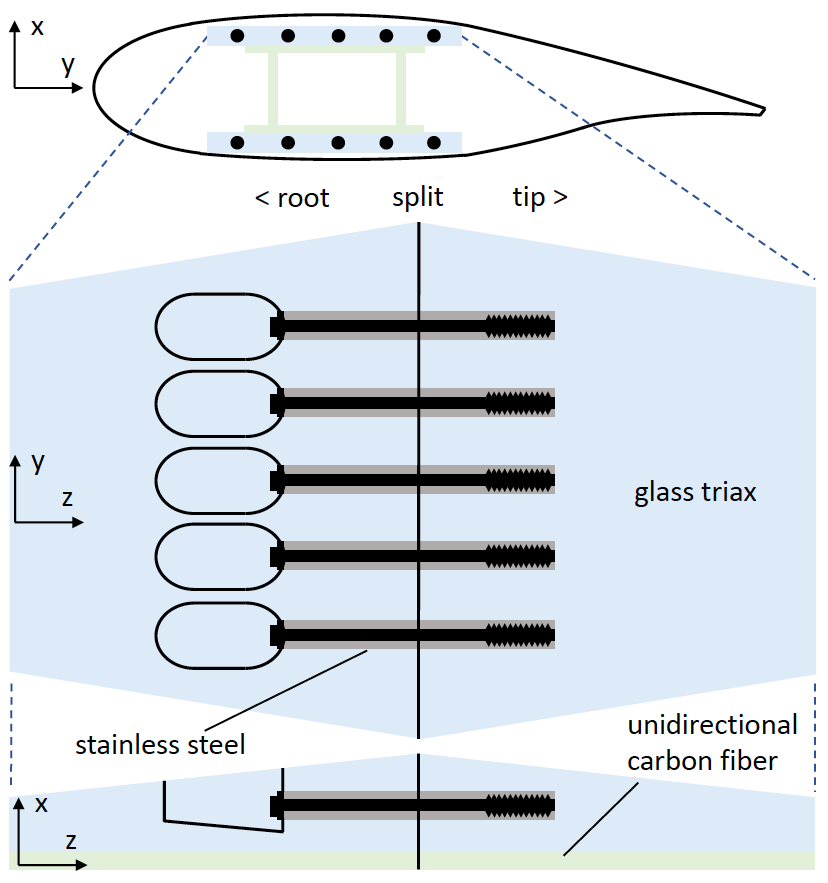
Fig. 48 On top, a cross-sectional view of the joint shows insert holes in the spar cap reinforcements. Below this, top and side views of half of the modelled embedded bushing joint, consisting of a spar cap, joint reinforcement, inserts, and bolts. Each insert is held in compression by a bolt and is glued to the root and tip sections of the reinforcement, which is enlarged to support the joint.
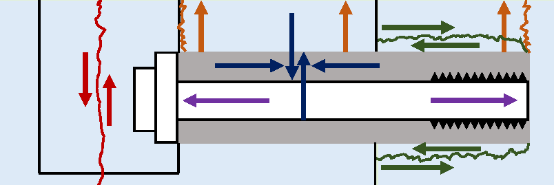
Fig. 49 The joint model calculates the number of bolt-insert pairs required to resist fatigue and ultimate failure, as well as the spar cap reinforcement width and thickness required to resist ultimate failure. The failure modes considered are bolt tensile failure, insert von Mises yield, insert shear-out through the top or bottom of the spar cap side, insert pull-through, and spar cap shear at the bolt head hole.
Inputs and Outputs
To model a wind turbine with segmented blades, the user specifies parameters in the geometry input .yaml file. The joint position, mass, bolt size, non-material cost adder, suction side reinforcement layer name, and pressure side reinforcement layer name are specified in the components>blade>internal_structure_2d_fem>joint dictionary. Details for these fields are below:
Position: [float] Spanwise normalized joint position. 0=root, 1=tip.
Mass: [float] (kg) Initial mass estimate of the joint bolts and inserts minus material mass removed from the sparcap and reinforcement layers to accommodate them (can be left as 0).
Bolt: [string] Select bolt type from M24, M30, M36, M42, M48, M52 bolts.
Nonmaterial_cost: [float] (USD) Accounts for added manufacturing, assembly, and transportation costs associated with the joint.
Reinforcement_layer_ss: [string] Spar cap suction side reinforcement layer name at the joint station.
Reinforcement_layer_ps: [string] Spar cap pressure side reinforcement layer name at the joint station.
Suction and pressure side reinforcement layers are named joint_reinf_ss and joint_reinf_ps, respectively, and are specified at components>blade>internal_structure_fem>layers. Joint insert material is named joint_insert and specified in the materials section. For an example segmented blade geometry input file, see the Big Adaptive Rotor project’s upwind segmented design with carbon fiber spar caps: WISDEM/examples/03_blade/BAR_USC.yaml. This design uses a glass triax reinforcement and steel joint inserts. The joint model calculates required spar cap suction side and pressure side reinforcement thicknesses, which the WISDEM optimizer can use as a constraint. Joint mass and cost are added as WISDEM outputs, below:
Rotorse.rs.bjs.joint_mass: [float] (kg) Mass of the joint bolts and inserts minus material mass removed from the reinforcement layers to accommodate them. Spar cap reinforcement material mass is considered separately.
Rotorse.rc.joint_material_cost: [float] (USD) Joint material cost (bolts + inserts + adhesive). Spar cap reinforcement material cost is considered separately.
Rotorse.rc.joint_cost: [float] (USD) Total cost of the joint (material plus non-material). Spar cap reinforcement material cost is considered separately.
Running Without Optimization
When running without optimization, the cost and mass fields can be set to 0. They will be populated in the output geometry .yaml file with the values calculated by WISDEM. A “Baseline Design” run without optimization can be found in Example 3 of this documentation.
Running With Optimization
When running with optimization, spar cap pressure and suction side thickness can be set as a design variable. Because of the way that blade hardware mass is calculated, it cannot be cycled through the optimization loop at this time. So, the optimization loop does not update blade hardware mass in each iteration. Therefore, we recommend running a baseline, non-optimization run to determine a rough joint mass, and then using this run’s output geometry .yaml file as the input geometry file for the optimization run. This 2-run process can be repeated to converge on a joint design, but we have found one process to be close to the converged design. “Baseline Design” and “Simple Structural Optimization“ instructions for the first and second runs, respectively, can be found in Example 3 of this documentation. We recommend using blade mass as the merit figure. The number of control points, specified in the analysis options .yaml file at design_variables>blade>structure>spar_cap_ss>n_opt and design_variables>blade>structure>spar_cap_ps>n_opt, should be selected so that one control point is at, or at least very close to, the joint station.