3. Drivetrain Components
This section describes the theory behind the sizing and estimation of mass properties for all of the hub and nacelle components. Unless otherwise noted, the moment of inertia expressions are about the component center of mass.
3.1. Hub
The hub is designed as the combination of a main flange and a spherical shell.
3.2. Spinner
The spinner is the aerodynamic cone that wraps around the hub.
3.3. Pitch System
The pitch system mass is an empirical estimation based on the blade mass and blade root bending moment. To find the mass in kilograms, \(m_{pitch}=0.22 m_{blade} n_{blade} + 12.6 |M_{root}| \rho / \sigma\) where \(|M_{root}|\) is the magnitude of the blade root bending moment (in Newton-meters), \(\rho\) is the density of the pitch bearing material, and \(\sigma\) is the yield stress.
The pitch system moment of inertia assumes that the mass is distributed as a solid ring at the hub diameter, so the moment of inertia about the hub center for axial and transverse values is,
3.4. Main Bearing(s)
This is a simple, regression-based sizing tool for the main bearings. The same function is called once for configurations with one main bearing or twice for configurations with two. It handles Compact Aligning Roller Bearings (CARB), Cylindrical Roller Bearings (CRB), Spherical Roller Bearings (SRB), and Tapered Roller Bearings (TRB). The face width, mass, and maximum allowable deflection angle of these bearing types are,
Type |
Face Width |
Mass |
Max Defl |
|---|---|---|---|
CARB |
\(0.2663 D_{shaft} + 0.0435\) |
\(1561.4 D_{shaft}^{2.6007}\) |
0.5 deg |
CRB |
\(0.1136 D_{shaft}\) |
\(304.19 D_{shaft}^{1.8885}\) |
2/3 deg |
SRB |
\(0.2762 D_{shaft}\) |
\(876.7 D_{shaft}^{1.7195}\) |
4.47 deg |
TRB |
\(0.1499 D_{shaft}\) |
\(543.01 D_{shaft}^{1.9043}\) |
1/20 deg |
In addition to the bearing mass, a bearing housing is assumed which scales the total mass value from the table by 3.963.
The bearing moment of inertia is assumed to be that of a generic torus, with axial and transverse values of,
Where \(R_{shaft}\) is assumed to be half of the face width from the table.
3.5. Low- and High-Speed Shafts
The low- and high-speed shaft diameter and thickness are user input values, with their length determined by the layout logic given other user inputs for tower top diameter and overhang distance. Since we allow for tapered shafts, the mass calculation is an integral along the shaft axis, \(m_{shaft} = \int_0^L \rho \pi [R_{shaft}(x)^2 - (R_{shaft}(x)-t_{shaft}(x))^2] dx\) , where \(\rho\) is the density of steel.
The shaft moment of inertia is assumed to be that of a generic hollow cylinder, with axial and transverse values of,
3.6. Gearbox
The gearbox design follows the general approach of the previous DriveSE implementation, however with code improvements, the results will likely be different than prior versions. The gearbox is assumed to have 3 stages, with the user specifying a configuration code of either “EEP” or “EPP”, with the “E” representing epicyclic (planetary) gear stages and “P” representing parallel gear stages. For the epicyclic stages, the user also has to specify the number of planets, so the EEP input would require something like [3, 3, 0] and EPP would require [3, 0, 0]. The user also specifies the overall target gear ratio, and then DrivetrainSE conducts a mass minimization of the three stage ratios that meet the target and minimize the overall mass.
The mass minimization is done in terms of an empirical estimate, previously presented in a number of papers suing the former DriveSE code. The mass of a single epicyclic or parallel stage is given by,
Where \(\tau_i\) is the input torque to the stage, \(U_i\) is the stage ratio, \(B\) is the number of planets, and \(\gamma\) is a safety factor equal to 1.1 for \(U_i<5\), otherwise 1.35.
The mass of the gearbox is the sum of the individual stage masses, plus estimates for the shrink disc and carrier masses, \(m_{shrinkdisc} = P_{turbine}/3\) and \(m_{carrier}=8000\), where \(P_{turbine}\) is the turbine rated power in kilowatts.
The gearbox moment of inertia is estimated assuming the gearbox is a solid cylinder, with axial and transverse values of,
This approach does not have the fidelity to estimate gearbox efficiency. This is therefore a user input value that is not affected by any of the calculations here.
3.7. Brake
The brake attaches to the high speed shaft for geared configurations or directly on the low speed shaft for direct drive configurations. It is regression based, but also allows for a user override of the total mass value. To obtain the brake mass in kilograms from the rotor torque in kilo-Newton meters (updated in 2020 by J. Keller), \(m_{brake} = 1.22 Q_{rotor}\).
The brake moment of inertia is taken from the equations of a solid disc with axial and transverse values of,
Where \(R_{disc}\) is assumed to be 1% of the blade length
3.8. Generator
The user has the option to select a simplified sizing of the generator, consistent with the level of fidelity of other components described here. However, a far more detailed and rigorous generator design approach is available through the GeneratorSE set of codes. The description of this methodology is beyond the scope of this document, and is best described in the original GeneratorSE report. Suffice to say here that this approach includes electromagnetic sizing and performance estimation, structural analysis and sizing through optimization constraints, basic thermal design, and more granular mass and cost roll-up. In this way the user can direct the optimizer to trade magnet, copper, and structural mass against one another to achieve the optimal generator design for a specific implementation and set of constraints. The user can choose from a number of different generator technologies:
PMSG-Outer: Permanent magnet synchronous generator (outer generator - inner stator)
PMSG-Disc: Permanent magnet synchronous generator (inner generator - outer stator) with solid disc stator support
PMSG-Arms: Permanent magnet synchronous generator (inner generator - outer stator) with arm/spoke stator support
EESG: Electrically excited synchronous generator
DFIG: Doubly fed induction generator
SCIG: Squirrel-cage induction generator
Each of the technologies have slightly different sets of required inputs that are best captured in the various examples. When doing detailed generator performance and sizing, the default technology for direct-drive configuration is PMSG-Outer and the for geared configurations it is DFIG.
When the user opts for the simplified generator model, the mass is estimated from either the rated torque or rated power. For the mass in kilograms and the rated power in kilowatts and rated torque in kilo-Newton meteers,
Generator performance is captured in the estimation of the mechanical-to-electrical conversion efficiency. This is reported as a function of rotational speed as a fraction of rated speed, but there is an allowance for user-override:
Where \(\eta\) is the efficiency and the constants are:
a |
b |
c |
|
Direct |
0.01007 |
0.06889 |
0.0200 |
Geared |
0.01289 |
0.0 |
0.0851 |
Whether doing detailed or simplified modeling of the generator, the moment of inertia is estimated in the same way. Like the gearbox, for the purposes of estimating the moment of inertia, the generator is assumed to be a solid cylinder, so the axial and transverse values are:
3.9. Generator Cooling
The generator cooling, or HVAC system, is a regression based mass estimate from the rated power, with an allowance for a user input override. To obtain the cooling mass in kilograms from the power in kilowatts, \(m_{cool} = 0.08 P_{turbine}\).
The cooling system moment of inertia is taken from the equations of a simple ring mass, assuming the cooling mass is located at about 75% of the outer generator radius, with axial and transverse values of,
3.10. Power Electronics
The power electronics (converter and transformer) are empirical, regression based estimates of mass from the rated power of the turbine. There is no electrical load analysis behind these estimates, but a user override of the total mass value can be provided. To obtain the mass in kilograms from the rated power in kiloWatts,
Where \(P_{turbine}\) is the rated power.
The moment of inertia for both converter and transformer assumes that each is a box with side lengths 1.5% of the rotor diameter. For all principal axes, the moment of inertia is \(I = m s^2 / 6\). Converter and transformer take on different moment of inertia values due to their different mass values.
3.11. Bedplate
Different bedplate models are used depending on if a geared or direct drive configuration is used. The height and length of the bedplate, regardless of configuration, is set by the user input dimensions such as overhang and desired height.
3.11.1. Geared
For geared layouts, the bedplate consists of twin I-beams that run along the bottom of the length of the nacelle. It is assumed that on top of these I-beams sits the platform, upon which the different nacelle sub-components are affixed at the appropriate location and tilt. The mass is the standard summation for I-beam cross sections,
Where \(w_f\) and \(t_f\) are the flange width and thickness and \(h_w\) and \(t_w\) are the web height and thickness, illustrated in n:numref:fig_ibeam_cross. The factor of two on the mass equation is to account for the twin I-beams.
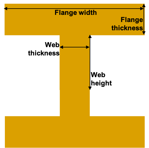
Fig. 3.1 I-beam cross section and dimension nomenclature.
The moment of inertia for the geared bedplate is taken from standard expressions for I-beam of a finite length with a coordinate system of \(x\) along the axial length, \(y\) consistent with a right-hand coordinate system when \(z\) is pointed up (from the base flange to the top flange),
Where \(\rho\) is the density of steel, \(y_{off}\) is the offset of the bedplate from the tower centerline, and \(D_{tt}\) is the diameter of the tower-top.
3.11.2. Direct-Drive
The direct-drive bedplate is a tapered elliptical cone that marries the nose (turret) to the yaw drive at the tower top. The choice of an elliptic cross-sections makes the steps to calculate the mass properties more involved, but using standard geometric equations.
The ellipse is defined in the x-z plane, with the centerline, outer curve, and inner curve defined by,
Where \(\theta\) is the parametric angle that varies from \([0,\pi/2]\) for standard upwind configurations or \([\pi,\pi/2]\) for downwind, \(L_{bedplate}\) is the major axis, and \(H_{bedplate}\) is the minor axis. The effective cross sectional diameter and area is approximated by,
To compute the mass, the area must be swept over the arc length of the ellipse. This calculation is made simpler by discretizing the ellipse into a series of arcs and using the average diameter and area in those arcs. The arcs are defined by the central angle relative to the origin, which is related to the parametric angle by, \(\tan \phi = (L_{bedplate}/H_{bedplate}) \tan \theta\). Arc lengths from the origin are calculated using incomplete elliptic integrals of the second kind, \(s = L_{bedplate} E(\phi, e)\), so the discrete arc segments are \(s_i = L_{bedplate} [E(\phi_i, e) - E(\phi_{i-1}, e)]\). The bedplate mass is finally \(\sum_i \rho s_i A_{bedplate,i}\) using the \(\rho\) as the density of steel.
The moment of inertia calculation for the elliptical bedplate could likely be approximated in multiple ways. With the assumption of an effective diameter and arc length, each segment was calculated as a cylindrical shell and then rotated from its angle, \(\phi_i\), to the tower top coordinate system.
3.12. Nacelle Platform
The nacelle platform that attaches to the bedplate to provide a floor for the nacelle is currently assumed to have a mass and moment of inertia of 1/8 of the bedplate.
3.13. Nacelle Cover
The nacelle cover dimensions are calculated by assuming the biggest element or component in each direction and adding 10% margin. Imagine a box that extends from one end of the bedplate to the hub flange and goes around the generator. The cover is assumed to be made of fiberglass that is 4cm thick. With these assumptions, the cover mass in kilograms can be calculated as,
Where \(D_{generator}\) is the outer diameter of the generator and the terms, \(\rho\) is the density of fiberglass, and \(L, W, H, A\) refer to the length, width, height, and area.
The moment of inertia of the nacelle cover is determined by assuming a hollow, rectangular box. The principal moments of inertia are then,
3.14. Yaw System
The yaw system is approximated by assuming that the main mass contributions are from the friction plate and the yaw motors. To obtain the yaw system mass in kilograms,
Where \(D_{rotor}\) is the rotor diameter in meters, \(D_{tt}\) is the tower-top diameter, and \(\rho\) is the density of steel. The friction plate mass calculation is derived from assuming that the surface width is 10% of the tower top diameter and the thickness is 0.1% of the rotor diameter.
Since the yaw system is at the tower top coordinate system origin, it is assumed to not contribute to the nacelle moment of inertia calculation.
3.15. Nacelle and RNA mass summary
To aid in the tower structural analysis, the total mass and moment of inertia of the nacelle is summed about a coordinate system center at the tower top. This is a straightforward summation of the mass, and a mass-weighted average of the component center of mass. For the component moments of inertia, which are given about the component center of mass, the inertia tensor was first rotated through the driveshaft tilt, and then the parallel axis theorem was applied to move from the component center of mass to the tower top coordinate system. These operations can be expressed as,
Where \(m_i\) is the component mass, \(\vec{r}_i\) is the vector from the tower top coordinate system origin to the component center of mass, \(I_i\) is the component moment of inertia tensor, \(R(\gamma)\) is the 3-D rotation matrix about the y-axis for the tilt angle, \(E_3\) is the 3x3 identity matrix, \(\cdot\) denotes the inner (dot) product, and \(\otimes\) denotes the outer product.