2. Layout and Inputs
The direct-drive and geared drivetrain layouts are quite different, however both use the same set of user inputs. This was intentional to simplify the user-input burden. The common layout parameters are,
Overhang (\(L_{overhang}\))
Height from hub to tower top (\(H_{htt}\))
Shaft tilt angle (\(\gamma\)),
Generator length (\(L_{generator}\))
Distance between the hub flange and the first main bearing (\(L_{h1}\))
Distance between the main bearings (\(L_{12}\))
Detailed diagrams of how these parameters set the sizing and layout of the drivetrain is shown in the two subsections below.
2.1. Direct-Drive Layout
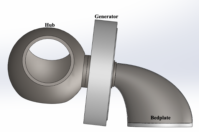
Fig. 2.1 Direct-drive configuration geometry
The overall layout for the direct-drive configuration is shown in Fig. 2.1 and Fig. 2.2. The hub connects to the low-speed shaft, which is a large diameter, hollow cylinder supported by two sets of main bearings attached to the nose, also called the turret. The nose is affixed to the bedplate, which also has a circular cross-section, but follows an elliptical curve down to the tower attachment. The total length, parallel to the ground, from the tower center line to the rotor apex, is considered the overhang. The total height difference between those same two points in the hub to tower top height. The outer-rotor of the generator also attaches to the low-speed shaft, and the corresponding stator attaches to the nose.
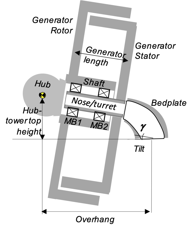
Fig. 2.2 Direct-drive configuration layout diagram
The detailed parameters that specify the drivetrain layout are shown in Fig. 2.3.
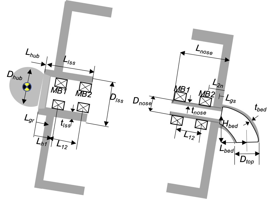
Fig. 2.3 Detailed direct-drive configuration with key user inputs and derived values.
In addition to the user-defined dimensions, the other values are derived in the following way,
Here the length from the hub flange to the generator rotor attachment, \(L_{grs}\), is assumed to be at the halfway point between the flange and the first main bearing, \(L_{h1}\). Similarly, the distance between the second main bearing and the nose/turret interface with the bedplate, \(L_{2n}\), is twice the distance as that from the same interface to the generator stator attachment, \(L_{gsn}\). After adding up the total length of the low speed shaft and nose/turret, the total drivetrain length from bedplate to hub can be determined. Then, the bedplate dimensions are determined in order to meet the target overhang and hub-to-tower top height. To ensure that these layout dimensions are adequately satisfied during a design optimization, a constraint is enforced such that \(L_{bed} \geq 0.5 D_{top}\).
The user must also specify diameter and thickness values for the low speed shaft (\(D_{lss}\) and \(t_{lss}\)) and the nose/turret (\(D_{nose}\) and \(t_{nose}\)). These can also be assigned as design variables to satisfy the constraints generated in the structural analysis.
The bedplate diagram is shown in Fig. 2.4, and follows an elliptical path from the tower top to the nose/turret attachment point. The length and height of the bedplate (major and minor half axes of the ellipse) are determined from the input user dimensions. The bedplate diameter also follows an elliptical progression from the tower top diameter at the bedplate base to the nose/turrent diameter at the top. The wall thickness schedule is a user defined input, or can be designated as a design variable in order to meet structural constraints.
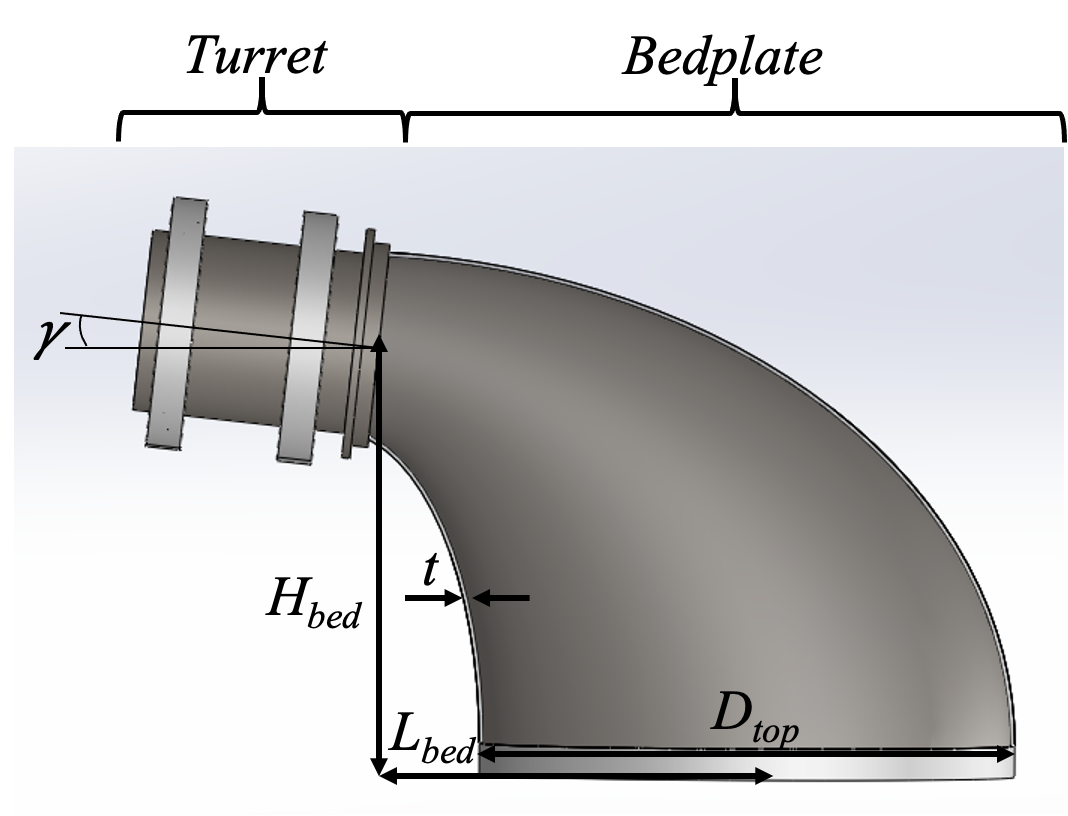
Fig. 2.4 Direct-drive configuration layout diagram
The attachment of the generator stator to the nose/turret is shown in Fig. 2.5. For the direct-drive configuration, we assume an outer rotor-inner stator, radial flux topology for a permanent magnet synchronous generator. The outer rotor layout facilitates a simple and rugged structure, easy manufacturing, short end windings, and better heat transfer between windings and teeth than an inner rotor configuration.
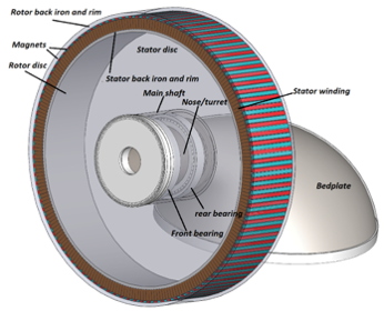
Fig. 2.5 Direct-drive configuration layout diagram
2.2. Geared Layout
The overall layout for the geared configuration is shown in Fig. 2.6. The hub connects to the low-speed shaft, supported by two sets of main bearings. The low speed shaft connects to the gearbox which converts the high-torque, low-rpm input into a low-torque, high-rpm output on the high speed shaft. The high speed shaft feeds the generator, which is assumed to be a doubly-fed induction generator (DFIG). The bedplate is a steel platform that sits atop two parallel I-beams to provide the structural support. The bearings and the generator are assumed to be firmly attached to the bedplate. The gearbox attaches to the nacelle platform atop the bedplate with a trunion.
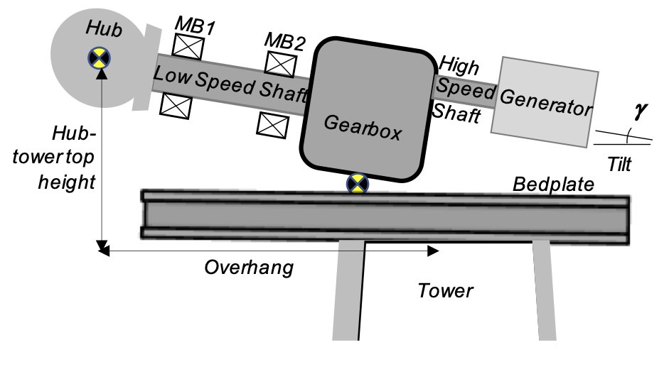
Fig. 2.6 Geared configuration layout diagram
The detailed parameters that specify the drivetrain geared are shown in Fig. 2.7.
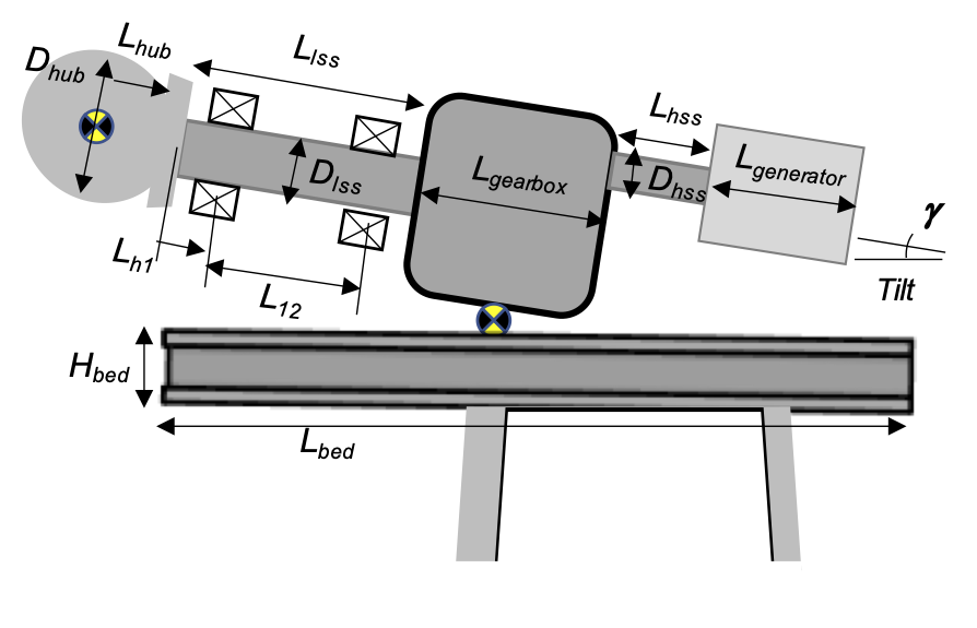
Fig. 2.7 Geared configuration layout diagram
In addition to the user-defined dimensions, the other values are derived in the following way,
The dimension, \(\delta\) is the space between the second main bearing and the gearbox attachment where the shrink disk lies. This is assumed to be 0.1 meters. The bedplate height is sized to ensure that the desired height from tower top to hub is obtained. To achieve the desired overhang distance, the tower is centered at the exact overhang distance from the hub and a constraint is enforced such that the drivetrain length is sufficient to extend past the tower, \(L_{drive} \cos \gamma - L_{overhang} \geq 0.5 D_{top}\).