4. Structural Analysis
The structural analysis in DrivetrainSE is where the largest differences with the previous DriveSE code lies. Instead of analytical derivations of the forces and moments on the various elements and closed form expressions for sizing the components, we instead rely on Frame3DD to conduct the analysis and enable the use of optimization with stress constraints to ensure a valid design. Separate analyses are run for the rotating and non-rotating parts of the drivetrain, with some small and large differences depending on whether a direct-drive or geared configuration is employed.
4.1. Rotating Structural Analysis
4.1.1. Low-Speed Shaft
The Frame3DD-based analysis of the rotating components attached to the low-speed shaft is illustrated in Fig. 4.1. It is assumed that the force and moment vectors applied to the hub are transferred to the low speed drive shaft. This shaft is supported by two sets of main bearings. The first main bearing absorbs all of the force components and the second absorbs the \(y\)- and \(z\)-moment components. These bearings, in turn, apply a reaction force on the shaft. The \(x\)-moment component is the shaft torque, which is taken on by either the generator rotor, in direct-drive configurations, or the gearbox, in geared configurations, giving the reaction \(M_g\). Near the gearbox/generator, there are also some weight loads applied. This is the brake system for direct-drive or the shrink disk and carrier in the geared configuration.
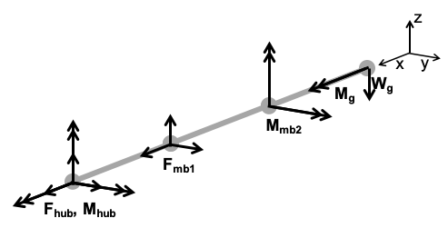
Fig. 4.1 Forces and reactions applied to low speed shaft (self weight gravitational load not shown).
Frame3DD determines the reaction forces and moments on the bearings and the stress along the shaft, from which a von Mises stress utilization constraint value is calculated, with a user-proscribed safety factor. The shaft deflection at the gearbox / generator stator connection is also saved as an output. This Frame3DD analysis uses a coordinate system such that the shaft lies along the x-axis (regardless of tilt), with the origin at the node on the far right where \(M_g\) is applied.
4.1.2. High-Speed Shaft
The high-speed shaft structural analysis is only done for geared drivetrain configurations. Compared to the low-speed shaft, it is also a much simpler analysis. The forces and moments are diagrammed in Fig. 4.2. It is assumed that the gearbox applies a pure torque on the shaft. This torque is the value of the torque applied to the low-speed shaft, divided by the gear ratio. The brake is attached to the high speed shaft, so its weight is applied at the shaft midpoint. The torque is absorbed by the generator, which applies a reaction torque in return.
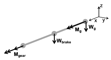
Fig. 4.2 Forces and reactions applied to high speed shaft (self weight gravitational load not shown).
Frame3DD determines the reaction moment and the stress along the shaft, from which a von Mises stress utilization constraint value is calculated, with a user-proscribed safety factor. The shaft deflection at the generator connection is also saved as an output. This Frame3DD analysis uses a coordinate system such that the shaft lies along the x-axis (regardless of tilt), with the origin at the generator connection node on the far right.
4.2. Stationary Structural Analysis
The structural analysis of the stationary drivetrain elements was split between direct-drive and geared configurations.
4.2.1. Direct-Drive
For direct-drive configurations, the force diagram modeled in Frame3DD is shown in Fig. 4.3. The forces and moments on the two main bearings, in addition to the bearing and housing weight, are transferred to the nose/turret. Additionally, the forces from the generator stator (usually just the weight) act on the nose/turret as well. The nose/turret is attached to the elliptically curved bedplate that is assumed to be fully clamped, with a corresponding reaction force. The weight force of all of the other nacelle components, such as the power electronics, bedplate, cooling system, fiberglass cover, etc. is also applied at the bedplate base.
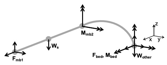
Fig. 4.3 Forces and reactions applied to the nose/turret and bedplate in a direct-drive configuration.
As with the rotating analysis, Frame3DD determines the bedplate reaction forces, which are then transferred to the tower in TowerSE analysis. A von Mises stress utilization constraint is computed along the nose/turret and the bedplate as well. Finally, deflections at the bearings and stator attachment are also computed and compared against any structural limits set by the choice of bearing or the GeneratorSE structural design. This Frame3DD analysis uses a coordinate system such that the bedplate base node is at (0, 0, 0).
4.2.2. Geared
For geared configurations, the force diagram modeled in Frame3DD is shown in Fig. 4.4. The forces and moments on the two main bearings, in addition to the bearing and housing weight, the gearbox, generator, cooling, brake, power electronics, and all other miscellaneous nacelle equipment are transferred to the twin I-beams. This is done by creating a “ghost nodes” in Frame3DD that receive these loads, then transfer them through perfectly rigid elements to the I-beams. The I-beams sit atop the yaw drive on the tower top, so are assumed to be fully clamped at those attachment points.
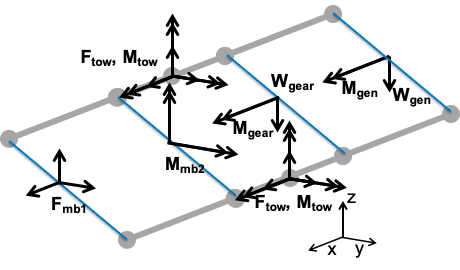
Fig. 4.4 Forces and reactions applied to the bedplate in a geared configuration.
Once the geared stationary analysis is described, the Frame3DD analysis and post-processing is similar to the direct-drive comments. Frame3DD determines the bedplate reaction forces, which are then transferred to the tower in TowerSE analysis. A von Mises stress utilization constraint is computed along the I-beams. Finally, deflections at the bearings and stator attachment are also computed and compared against any structural limits set by the choice of bearing or the GeneratorSE structural design. This Frame3DD analysis uses a coordinate system such that the center of the tower center axis is at (0, 0, 0).