Optimization
Executing FloatingSE by hand is sufficient to explore some simple one-off or comparison analyses between a few runs. OpenMDAO provides extensive optimization capability, which can give yield richer and more insightful analyses.
Design Variables
In WISDEM, via OpenMDAO, any input parameter can be designated a design variable. The design variables used in this study focused on the geometric specification of the floating substructure and mooring subsystem. Slightly different design variables and bounds were used for spar, semisubmersible, and TLP optimizations. The complete listing of the design variables for each optimization configuration is shown in Table 8. Note that the integer design variables were only used in the global optimization with the genetic algorithm, not the local search with the simplex algorithm.
Variable |
Name |
Units |
Type |
Bounds |
|---|---|---|---|---|
Main col section height |
|
Float array (\(n_s\)) |
0.1–50 |
|
Main col outer diameter |
|
Float array (\(n_s+1\)) |
2.1–40 |
|
Main col wall thickness |
|
Float array (\(n_s+1\)) |
0.001–0.5 |
|
Main col freeboard |
|
Float scalar |
0–50 |
|
Main col stiffener web height |
|
Float array (\(n_s\)) |
0.01–1 |
|
Main col stiffener web thickness |
|
Float array (\(n_s\)) |
0.001–0.5 |
|
Main col stiffener flange width |
|
Float array (\(n_s\)) |
0.01–5 |
|
Main col stiffener flange thickness |
|
Float array (\(n_s\)) |
0.001–0.5 |
|
Main col stiffener spacing |
|
Float array (\(n_s\)) |
0.1–100 |
|
Main col permanent ballast height |
|
Float scalar |
0.1–50 |
|
Main col buoyancy tank diameter |
|
Float scalar |
0–50 |
|
Main col buoyancy tank height |
|
Float scalar |
0–20 |
|
Main col buoyancy tank location (fraction) |
|
Float scalar |
0–1 |
|
Number of offset cols |
|
Integer scalar |
3-5 |
|
Offset col section height |
|
Float array (\(n_s\)) |
0.1–50 |
|
Offset col outer diameter |
|
Float array (\(n_s+1\)) |
1.1–40 |
|
Offset col wall thickness |
|
Float array (\(n_s+1\)) |
0.001–0.5 |
|
Offset col freeboard |
|
Float scalar |
2–15 |
|
Offset col stiffener web height |
|
Float array (\(n_s\)) |
0.01–1 |
|
Offset col stiffener web thickness |
|
Float array (\(n_s\)) |
0.001–0.5 |
|
Offset col stiffener flange width |
|
Float array (\(n_s\)) |
0.01–5 |
|
Offset col stiffener flange thickness |
|
Float array (\(n_s\)) |
0.001–0.5 |
|
Offset col stiffener spacing |
|
Float array (\(n_s\)) |
0.01–100 |
|
Offset col permanent ballast height |
|
Float scalar |
0.1–50 |
|
Offset col buoyancy tank diameter |
|
Float scalar |
0–50 |
|
Offset col buoyancy tank height |
|
Float scalar |
0–20 |
|
Offset col buoyancy tank location (fraction) |
|
Float scalar |
0–1 |
|
Radius to offset col |
|
Float scalar |
5–100 |
|
Pontoon outer diameter |
|
Float scalar |
0.1–10 |
|
Pontoon wall thickness |
|
Float scalar |
0.01–1 |
|
Lower main-offset pontoons |
|
Integer scalar |
0–1 |
|
Upper main-offset pontoons |
|
Integer scalar |
0–1 |
|
Cross main-offset pontoons |
|
Integer scalar |
0–1 |
|
Lower offset ring pontoons |
|
Integer scalar |
0–1 |
|
Upper offset ring pontoons |
|
Integer scalar |
0–1 |
|
Outer V-pontoons |
|
Integer scalar |
0–1 |
|
Main col pontoon attach lower (fraction) |
|
Float scalar |
0–0.5 |
|
Main col pontoon attach upper (fraction) |
|
Float scalar |
0.5–1 |
|
Fairlead (fraction) |
|
Float scalar |
0–1 |
|
Fairlead offset from col |
|
Float scalar |
5–30 |
|
Fairlead pontoon diameter |
|
Float scalar |
0.1–10 |
|
Fairlead pontoon wall thickness |
|
Float scalar |
0.001–1 |
|
Number of mooring connections |
|
Integer scalar |
3–5 |
|
Mooring lines per connection |
|
Integer scalar |
1–3 |
|
Mooring diameter |
|
Float scalar |
0.05–2 |
|
Mooring line length |
|
Float scalar |
0–3000 |
|
Anchor distance |
|
Float scalar |
0–5000 |
Constraints
Due to the many design variables, permutations of settings, and applied physics, there are many constraints that must be applied for an optimization to close. The constraints capture both physical limitations, such as column buckling, but also inject industry standards, guidelines, and lessons learned from engineering experience into the optimization. As described in the Introduction, this is a critically important element in building a MDAO framework for conceptual design that yields feasible results worth interrogating further with higher-fidelity tools. The constraints used in the substructure design optimization and sensitivity studies are listed in Table 9. Where appropriate, some of the constraint values differ from one type of substructure to another. Some additional explanation is provided for a handful of constraints in the subsections below.
Lower |
Variable |
Upper |
Comments |
|---|---|---|---|
Tower / Main / Offset Columns |
|||
Eurocode global buckling |
1.0 |
||
Eurocode shell buckling |
1.0 |
||
Eurocode stress limit |
1.0 |
||
Manufacturability |
0.5 |
Taper ratio limit |
|
120.0 |
Weld-ability |
Diameter:thickness ratio limit |
|
Main / Offset Columns |
|||
Draft ratio |
1.0 |
Ratio of draft to max value |
|
API 2U general buckling- axial loads |
1.0 |
||
API 2U local buckling- axial loads |
1.0 |
||
API 2U general buckling- external loads |
1.0 |
||
API 2U local buckling- external loads |
1.0 |
||
Wave height:freeboard ratio |
1.0 |
Maximum wave height relative to freeboard |
|
1.0 |
Stiffener flange compactness |
||
1.0 |
Stiffener web compactness |
||
Stiffener flange spacing ratio |
1.0 |
Stiffener spacing relative to flange width |
|
Stiffener radius ratio |
0.50 |
Stiffener height relative to diameter |
|
Offset Columns |
Semi only |
||
0.0 |
Heel freeboard margin |
Height required to stay above waterline at max heel |
|
0.0 |
Heel draft margin |
Draft required to stay submerged at max heel |
|
Pontoons |
Semi only |
||
Eurocode stress limit |
1.0 |
||
Tower |
|||
-0.01 |
Hub height error |
0.01 |
|
Mooring |
|||
0.0 |
Axial stress limit |
1.0 |
|
Line length limit |
1.0 |
Loss of tension or catenary hang |
|
Heel moment ratio |
1.0 |
Ratio of overturning moment to restoring moment |
|
Surge force ratio |
1.0 |
Ratio of surge force to restoring force |
|
Geometry |
|||
1.0 |
Main-offset spacing |
Minimum spacing between main and offset columns |
|
0.0 |
Nacelle transition buffer |
Tower diameter limit at nacelle junction |
|
-1.0 |
Tower transition buffer |
1.0 |
Diameter consistency at freeboard point |
Stability |
|||
0.10 |
Metacentric height |
Not applied to TLPs |
|
1.0 |
Wave-Eigenmode boundary (upper) |
Natural frequencies below wave frequency range |
|
Wave-Eigenmode boundary (lower) |
1.0 |
Natural frequencies above wave frequency range |
|
0.0 |
Water ballast height limit |
1.0 |
|
0.0 |
Water ballast mass |
Neutral buoyancy |
Geometry Constraints
Words Table 10
Variable |
Type |
Description |
|
Float scalar |
Maximum allowable draft for the substructure |
Manufacturing Constraints
Manufacturing steel frustum shells requires rolling steel plates into shape and welding along a seam to close the section. To accommodate traditional rolling and welding practices, both the diameter taper over the course of a section and the wall thickness ratio relative to the diameter are capped. Similarly, to facilitate welding the semisubmersible pontoons to the columns, constraints regarding the radio of diameters between the two are enforced. These limits are determined by user parameters in Table 11 and constraints,
Variable |
Type |
Description |
|
Float scalar |
For manufacturability of rolling steel |
|
Float scalar |
For weld-ability |
|
Float scalar |
For welding pontoons to columns |
Stress Limits and Code Compliance
The stress and buckling code compliance constraints are formulated as utilization ratios (ratio of actual to maximum values), with a safety factor, which must be less than one. The safety factor parameters are listed in Table 12.
Variable |
Type |
Description |
|
Float scalar |
Safety factor on |
|
Float scalar |
Safety factor on buckling |
|
Float scalar |
Safety factor on materials |
|
Float scalar |
Safety factor on consequence of failure |
|
Float scalar |
Not currently used |
Stability
As described above, surge and pitch stability are enforced through similar approaches. The total force and moment acting on the turbine are compared to the restoring forces and moments applied by the mooring system, buoyancy, or other sources at the maximum allowable point of displacement. These constraints are formulated as ratios with the user specifying the maximum allowable limits via the variables in Table 13.
Variable |
Type |
Units |
Description |
|
Float scalar |
\(m\) |
Max surge/sway offset |
|
Float scalar |
\(deg\) |
Max heel (pitching) angle in operating conditions |
|
Float scalar |
\(deg\) |
Max heel (pitching) angle in parked conditions |
Objectives
Different anaylses will emphasize different metrics, requiring different
objective functions. Under the default assumption that the user wishes
to minimize cost and adhere to stability constraints, the objective
function would be total substructure cost (variable name,
total_cost) or mass (variable name, total_mass).
Example
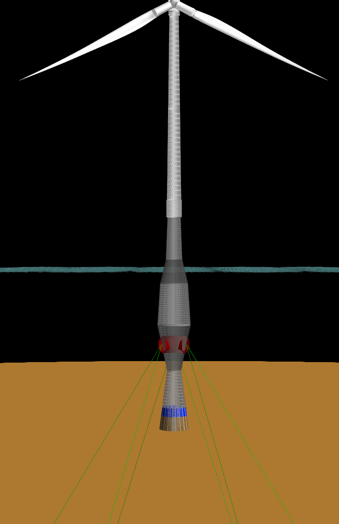
Fig. 43 Example of optimized spar.
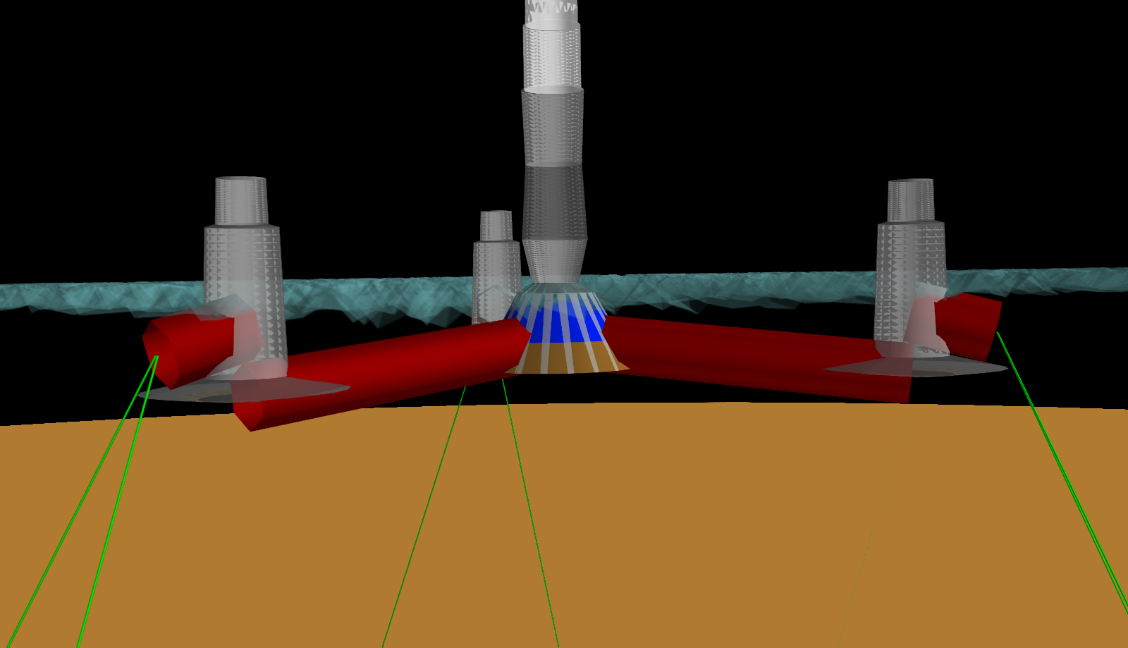
Fig. 44 Example of optimized semi.
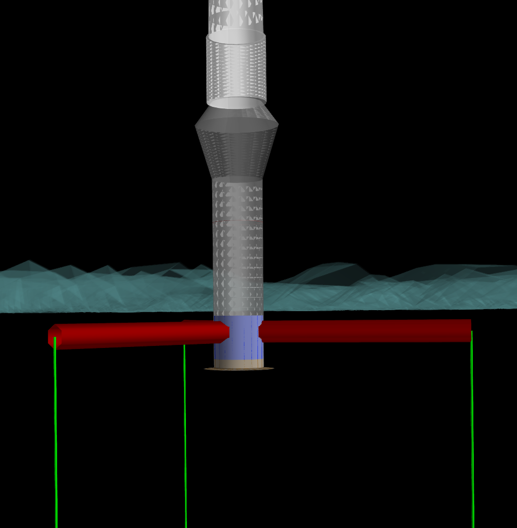
Fig. 45 Example of optimized TLP.