Execution
Executing FloatingSE requires additional inputs beyond those of the geometry definition described above in Section Geometry. Other user inputs for the metocean and loading environment, and the operational constraints, are required to evaluate the total mass, cost, and code compliance. These variables are also included in the WindIO effort or found in the floating-specific examples for standalone execution.
Simulation Flow
Once the input variables are completely specified, FloatingSE executes the analysis of the substructure. Conceptually, the simulation is organized by the flowchart in Fig. 40.
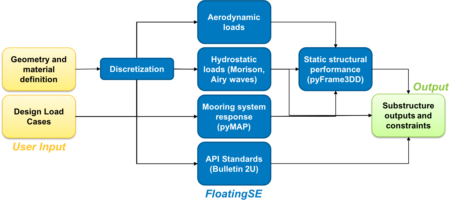
Fig. 40 Conceptual diagram of FloatingSE execution.
From a more technical perspective, FloatingSE is an OpenMDAO Group, so the analysis sequence is broken down by the sub-groups and sub-components in the order that they are listed in Table [tbl:exec]. In an OpenMDAO group, sub-groups and components are given prefixes to aid in referring to specific variables. The prefixes used in FloatingSE are also listed in Table 7.
Prefix |
Name |
Description |
|
|---|---|---|---|
|
TowerLeanSE |
Discretization of tower geometry (but no analysis) |
|
|
Column |
Discretization and API Bulletin 2U compliance of main.vertical column |
|
|
Column |
Discretization and API Bulletin 2U compliance of offset columns |
|
|
SubstructureGeometry |
Geometrical constraints on substructure |
|
|
MapMooring |
Mooring system analysis via pyMAP |
|
|
FloatingLoading |
Structural analysis of complete floating turbine load path via pyFrame3DD |
|
|
Substructure |
Static stability and final mass and cost summation for generic substructure |
Outputs are accumulated in each sub-group or component, and they either become inputs to other components, become constraints for optimization problems, become design variables for optimization problems, or can simply be ignored. Currently, a single execution of FloatingSE takes only a handful of seconds on a modern laptop computer.
Examples
As mentioned previously floating-specific examples examples are provided. These files are encoded with default starting configurations (from [Jon10] and [RJM+14], respectively), with some modifications. There is an additional spar example that also has a ready configurations for optimization with design variables, constraints, and solvers options. A visualization of the geometries described by these examples is shown in Fig. 41 and Fig. 42.
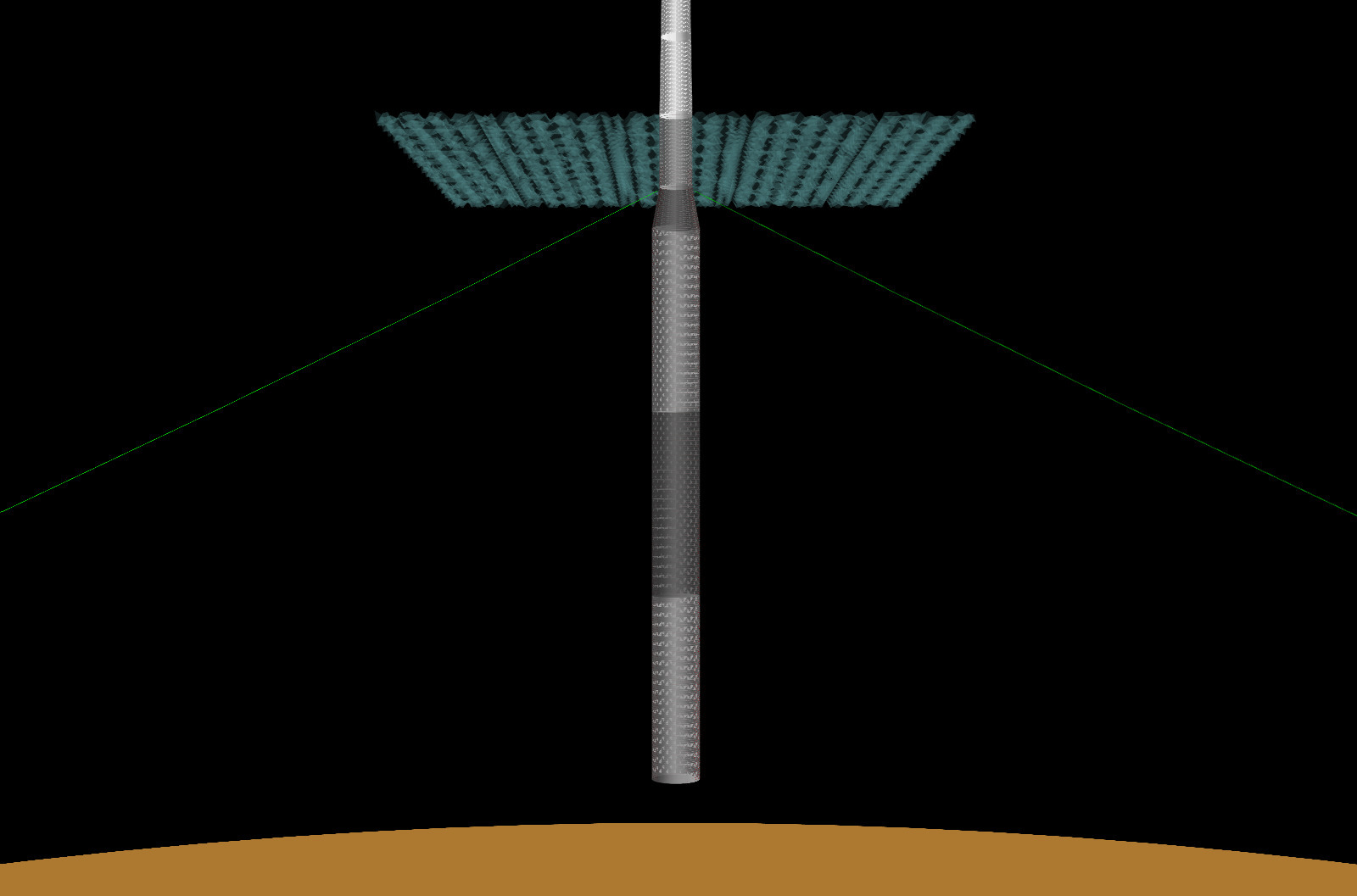
Fig. 41 Spar example in FloatingSE taken from OC3 [Jon10] project.
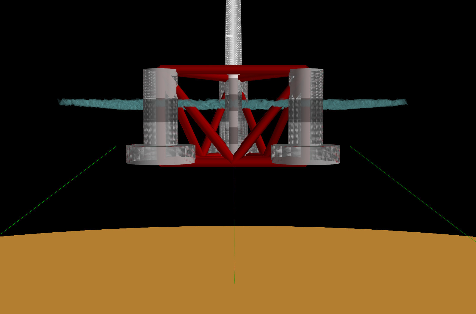
Fig. 42 Semi example in FloatingSE taken from OC4 [RJM+14] project.
Jason Jonkman. Definition of the floating system for phase IV of OC3. Technical Report NREL/TP-500-47535, National Renewable Energy Lab.(NREL), Golden, CO, May 2010. URL: https://www.nrel.gov/docs/fy10osti/47535.pdf.
A. Robertson, J. Jonkman, M. Masciola, H. Song, A. Goupee, A. Coulling, and C. Luan. Definition of the semisubmersible floating system for phase II of OC4. Technical Report NREL/TP-5000-60601, National Renewable Energy Lab.(NREL), Golden, CO, July 2014. URL: https://www.nrel.gov/docs/fy14osti/60601.pdf.