Geometry
This section describes the variables and methods used to parameterize the substructure geometry in FloatingSE. Typically, substructure designs have fallen into three classical regimes, which are shown in Fig. 30, each of which attains static stability through different physical mechanisms. A spar derives its stability from a deep drafted ballast. A semisubmersible derives its stability from distributed waterplane area, achieved with offset columns spread evenly around a main column or central point. A tension leg platform (TLP) uses taut mooring lines for its stability.
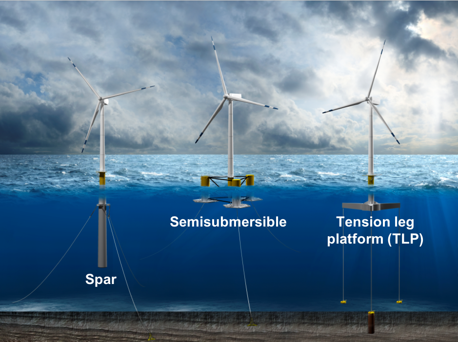
Fig. 30 Three classical designs for floating turbine substructures.
Similar to [KHBC17], care was taken to parameterize the substructure in a general manner, so as to be able to use the same set of design variables to describe spars, semisubmersibles, TLPs, and hybrids of those archetypes. The intent is that this modular approach to substructure definition will enable rapid analysis of the majority of designs currently proposed by the floating wind development community, whether classical or novel in nature. Furthermore, generalizing the substructure definition also empowers the optimization algorithm to search a broad tradespace more efficiently by moving fluidly from one region to another.
With that intent in mind, the general configuration of a spar-type substructure is shown in Fig. 31, with nomenclature borrowed from the field of naval architecture. A semisubmersible configuration would have a similar diagram, but with multiple offset columns connected with pontoon elements. A TLP might look similar to a spar or semisubmersible, with taut mooring lines instead of the catenary ones shown.
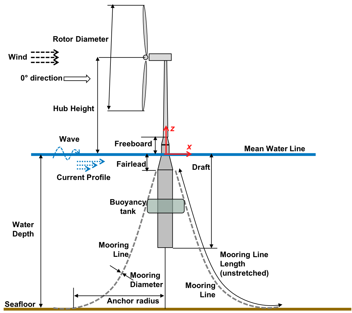
Fig. 31 Geometry parameterization with common wind turbine and naval architecture conventions.
Inputs: WindIO
The parameterization of the input variables in the Geometry YAML file into FloatingSE is documented within the larger WindIO effort. When running FloatingSE directly as a standalone with a python script, users are encouraged to review the floating-specific examples for syntax.
Tapered Cylinders (Vertical Frustums)
A number of typical floating substructure designs, such as the spar or semisubmersible, contain vertically oriented columns. In FloatingSE, these columns are assumed to have a circular cross-section making them, formally, vertical frustums. These frustums are assumed to be ring-stiffened to support the buckling loads inherent in a submerged support structure. The number of columns, their geometry, and the ring stiffeners are parameterized in the FloatingSE module according to the diagrams in Fig. 31, Fig. 32, Fig. 33, and Fig. 34. The main column is assumed to be centered at \((x=0, y=0)\), directly underneath the turbine tower (note that off-centered turbines are not yet supported). Other columns are referred to as offset columns, and are assumed to be evenly spread around the main column. The material of the vertical columns is currently assumed to be ASTM 992 steel. Future developments will include the option to select one of multiple material options for each section in each cylinder.
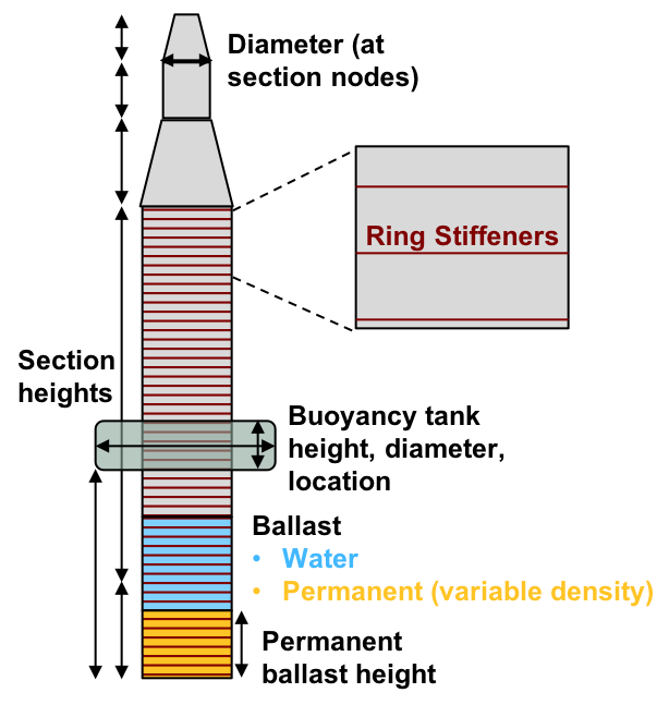
Fig. 32 Vertical frustum geometry parameterization.
Discretization
To allow for varying geometry parameters along the length of substructure columns, the larger components are divided into sections. The user may specify the number of overall sections, \(n_s\) and the geometry of each section. Some of the geometry parameters are tied to the nodes that bracket each section, such as column diameter and wall thickness, with linear variation between each node. Other parameters are considered constant within each section, such as the spacing between ring stiffeners. The number of sections should resemble the physical number of cans or sections used in the manufacturing of the real article.
Stiffeners
The ring stiffener geometry is depicted in Fig. 33, and Fig. 34.
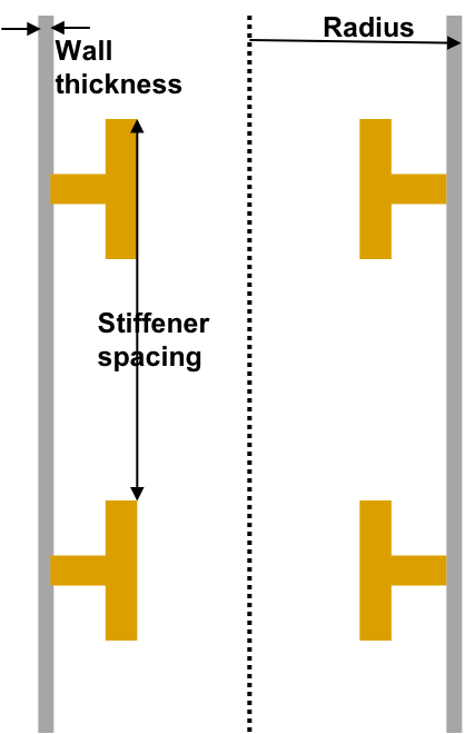
Fig. 33 Vertical frustum cross-section with stiffeners
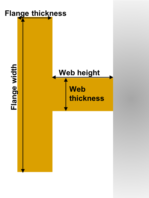
Fig. 34 Vertical frustum stiffener geometry parameterization.
Material Properties
The material of the vertical columns is commonly assumed to uniformly be ASTM 992 steel. Careful selection of the layering in the yaml-file inputs allows for much more complex material selections for different parts of the platform.
Ballast
Stability of substructure columns with long drafts can be enhanced by placing heavy ballast, such as magnetite iron ore, at their bottom sections. The user can specify the density of the permanent ballast added and the height of the ballast extent within the column. Variable ballast, as opposed to permanent ballast, is water that is added or removed above the permanent ballast to achieve neutral buoyancy as the operating conditions of the turbine change. A discussion of variable water balance in the model is found in Section Hydrostatic Stability.
Buoyancy Tanks (and Heave Plates)
Buoyancy tanks are modeled as a collar around the column and are not subject the same taper or connectivity constraints as the frustum sections. They therefore offer added buoyancy without incurring as much structural mass or cost. Moreover, they can also serve to augment the heave added mass like a plate. In addition to their diameter and height, the user can adjust the location of the buoyancy tank from the column base to the top. Buoyancy tanks can be added to either the main and/or offset columns.
Pontoons and Support Structure
Many substructure designs include the use of pontoons that form a truss to connect the different components, usually columns, together. In this model, all of the pontoons are assumed to have the identical thin-walled tube cross section and made of the same material as the rest of the substructure. The truss configuration and the parameterization of the pontoon elements is based on the members shown in Fig. 35 with lettered labels. The members are broken out into the upper and lower rings connecting the offset columns (\(B\) and \(D\), respectively), the upper and lower main-to-offset connections (\(A\) and \(C\), respectively), the lower-base to upper-offset cross members (\(E\)), and the V-shaped cross members between offset columns (\(F\)).
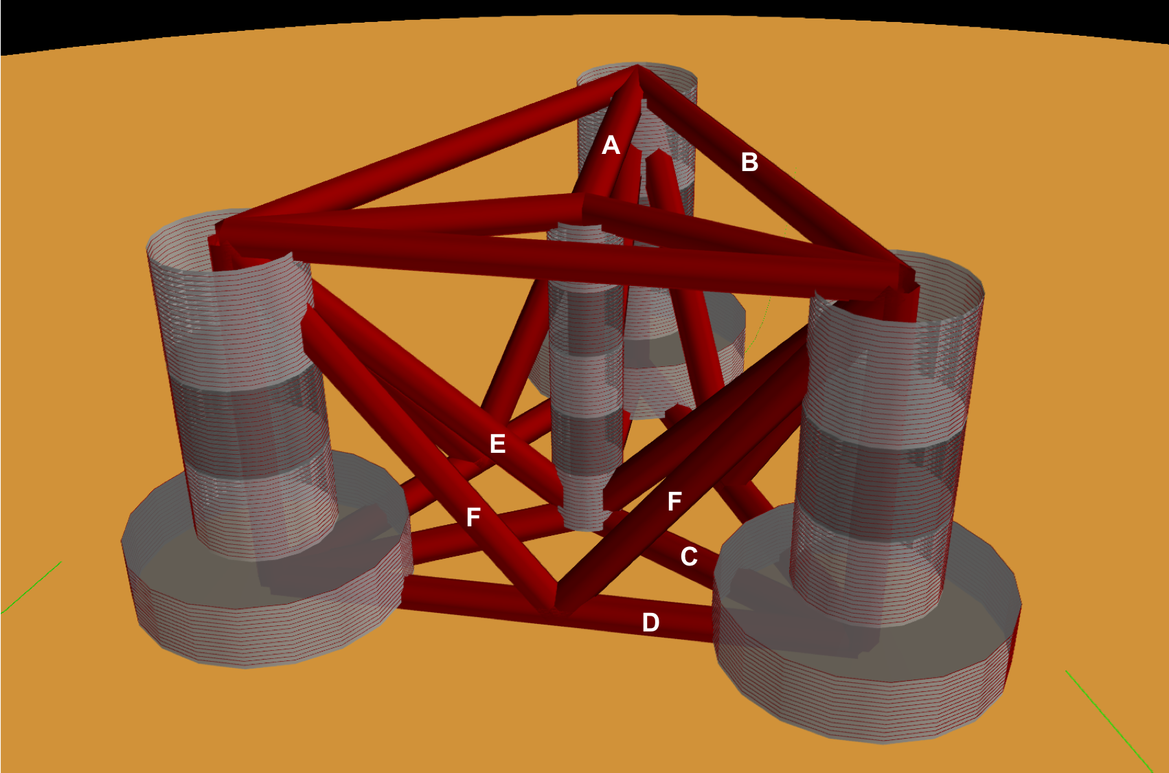
Fig. 35 Parameterization of truss elements in substructure.
Mooring Lines
The mooring system is described by the number of lines, their geometry, and their interface to the substructure. The mooring diameter is set by the user and determines the breaking load and stiffness of the chain, via correlation, described in Section Theory. The mooring lines attach to the substructure at the fairlead distance below the water plane, as shown in Fig. 31. The lines can attach directly to a substructure column or at a some offset from the outer shell. Note that bridle connections are not yet implemented in the model. The mooring lines attach to the sea floor at a variable distance, the anchor radius, from the substructure centerline, also set by the user.
By default, the mooring system is assumed to use a steel chain with drag embedment anchors. Other mooring available for selection are nylon, polyester, steel wire rope (IWRC) and fiber-core wire rope. The only alternative anchor type is currently suction pile anchors, but there are plans to include gravity anchors as well. The standard configuration for TLPs is the use of taut nylon mooring lines with suction-pile anchors.
Mass and Cost Scaling
The mass of all components in the modeled substructure is captured through calculation of each components’ volume and multiplying by its material density. This applies to the frustum shells, the ring stiffeners, the permanent ballast, the pontoons, and the mooring lines. However, the model also acknowledges that the modeled substructure is merely an approximation of an actual substructure and various secondary elements are not captured. These include ladders, walkways, handles, finishing, paint, wiring, etc. To account for these features en masse, multipliers of component masses are offered as parameters for the user as well. Capital cost for all substructure components except the mooring system is assumed to be a linear scaling of the components masses. For the mooring system, cost is dependent on the tension carrying capacity of the line, which itself is an empirical function of the diameter. Cost factors are especially difficult to estimate given the proprietary nature of commercial cost data, so cost rates and estimates should be considered notional.
Meysam Karimi, Matthew Hall, Brad Buckham, and Curran Crawford. A multi-objective design optimization approach for floating offshore wind turbine support structures. Journal of Ocean Engineering and Marine Energy, 3(1):69–87, Feb 2017. doi:10.1007/s40722-016-0072-4.